TAB-WELDING
Scan-system for laser welding on battery cells
Which scan system is suitable for laser welding on battery cells?
It‘s about making contact - safe and fast welding processes in e-mobility
Laser welding is a vital component in electromobility. The battery should fully charge as quickly as possible, at the highest possible load capacity, with the longest possible range. But where electricity flows, there is always electrical resistance. This can drastically reduce the efficiency of a battery. Particularly when many small individual battery cells or submodules are connected in series to form a larger cell system, this resistance can quickly become a major problem. Which solutions does RAYLASE offer for the laser welding of battery cells?
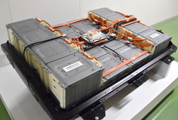
THE BEST LASER WELDED JOINT -
TAB WELDING AND CELL CONNECTION
Different cell formats are currently used for batteries depending on the manufacturer and requirements: cylindrical, also called round cells, pouch, and prismatic cells. What they all have in common is: through-hole plating the electrodes by means of cell arrestors „tabs“, or cell connectors in prismatic cells. The most important aspect here is to achieve high quality, fully reproducible welds of the individual cells, which do not form any contact resistances so that the electricity current can flow unhindered.
PRODUCT SOLUTIONS:
RAYLASE offers highly effective scan systems in e-mobility for welding processes on battery cells:
- AXIALSCAN FIBER-20 / -30
- Steuerkarte SP-ICE-3
- Lasersoftware RAYGUIDE
OPTIMUM THROUGH-HOLE PLATING OF CYLINDRICAL CELLS
Cylindrical cells in the currently common designs 18650 or 21700 are connected in parallel extensively over a large area via current conducting plates to increase the available storage capacity. Copper is used as the material for the current conducting plates due to its high conductivity. The parallel-connected cylindrical cells form a submodule and are serially connected in further production steps to form a „battery pack“. With cylindrical cells, the welding process should not be underestimated, as the contact sheets are very thin. Therefore, the welding depth must be maintained with absolute precision.
The series connection of the cells now enables the source voltages of the submodules to be accumulated. These units can be controlled with other cell systems, e.g. in the floor assembly of an electric vehicle, and interconnected as requi- red via the power electronics. Only laser deflection units can stably reproduce these highly complex work steps.
LASER WELDING OF CYLINDRICAL CELLS
In addition to other common processes such as friction welding and ultrasonic welding, laser micro welding with laser deflection units such as the RAYLASE AXIALSCAN FIBER in particular offers a welding process without the application of mechanical force for fine structures with thin sheets, as is the case with cylindrical cells. Depth welding processes are used here in particular, in which the laser beam penetrates both sheets to be welded with a very small spot diameter but remains in the lower sheet with a defined welding depth. A socalled „keyhole“ is formed, a welding capillary that fills up with the liquefied metal mixture and cools down as soon as the laser beam moves away. The laser beam is modulated or wobbled to increase the connection area to a precisely defined value. Suitable deflection units therefore have both a high jumping speed from contact point to contact point and a high wobbling speed with very good positioning accuracy. Specific deflection units are unbeatable here. Single mode or single mode near laser are used.
Good cohesion - welding different materials
A special feature in the welding process of different cell formats is the welding of „dissimilar“ materials, such as copper current conducting plates with aluminium terminals. The different degrees of absorption of the metals for the laser wavelength used result in a different melting behaviour. With the challenge of joining the copper to the aluminium without welding through. This is also the case with another cell format, the pouch cells. The tabs of the pouch cells are designed as contact tabs made of aluminium or copper, depending on the terminal.
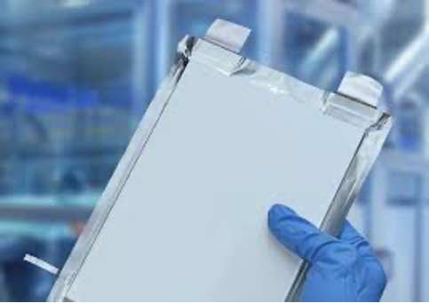
Pouch cells with contact tabs | Source Fraunhofer Allianz Batterie
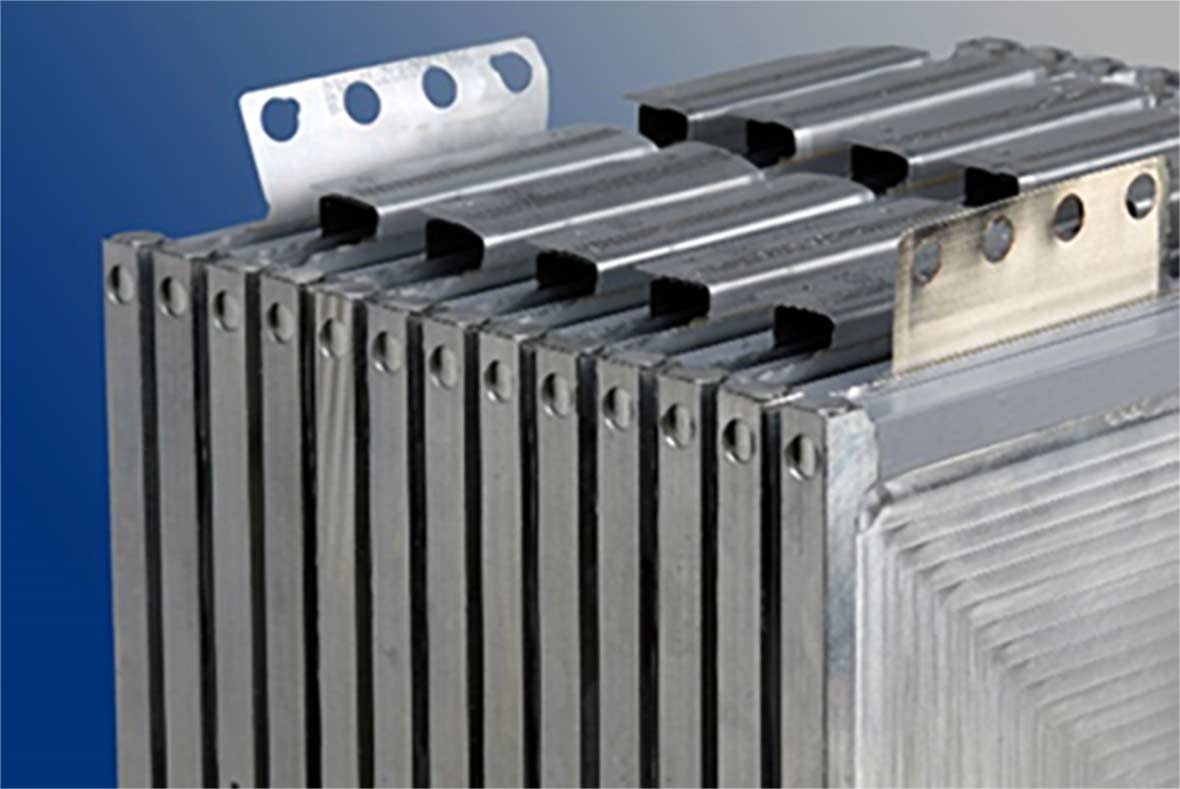
Cell system of pouch cells | Source ILT Aachen
POUCH CELLS – STORED SIDE BY SIDE
In contrast to cylindrical cells, pouch cells are installed side by side with very good thermal contact in a battery pack and welded in series via their „tabs“. The pack must be cooled accordingly, otherwise there is a risk that the pouches will swell under high electrical load and cause damage. This makes pouch cells more expensive overall. However, the foil stack of a pouch cell offers a very high cell loading capacity. A parallel connection is therefore not necessary, except when there is an additional need, for example, to increase the mileage of an e-vehicle.
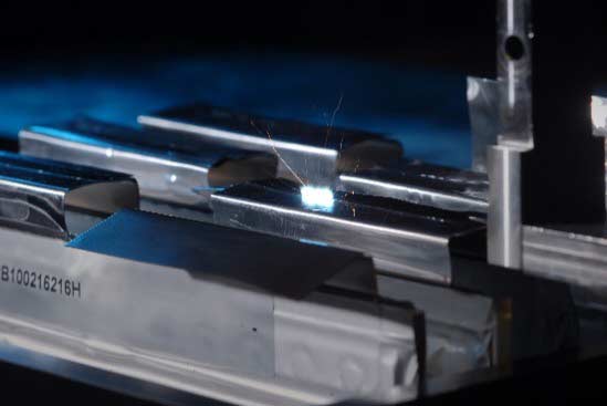
Welding process for pouch cells | Source ILT Aachen
Most commonly, heat conduction welding is used for pouch cells. This is always possible if the tabs have sufficient thickness to produce a very robust welded joint with relatively high laser power. The heat conduction process results in a weld bead width of several 100 micrometres.
Since pouch cells take up less space, multi-mode lasers up to 6 kW are used here. They guarantee a high-quality connection with very good electrical contact - thanks to the laser.
PRISMATIC CELLS - CELL CONNECTORS IN CONTACT
The prismatic cells also have a foil wrapping like the cylindrical cells, however this is not round, it lies horizontally in a very robust housing. This makes this cell format very safe, and at the same time requires more space. Apart from cars, the main application areas are forklift trucks, trucks, buses, and ships. The prismatic cells are also installed side by side to form a battery pack and then contacted in series via so-called „cell connectors“. Since aluminium is welded with aluminium here, modulated heat conduction welding with a multi-kW laser is often used in production.
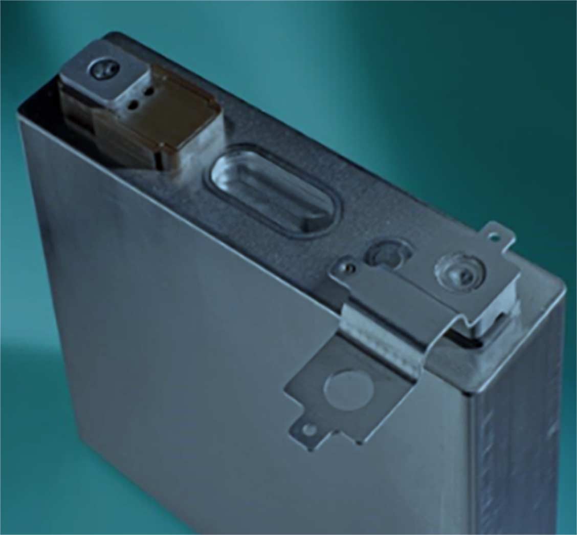
Prismatic cells | Source Fraunhofer ILT Aachen
DEFLECTION UNITS - KEEPING AN EYE ON THE LASER
Which deflection unit fits which job is determined by the desired parameters such as laser process field size in combination with the laser spot size. The machine manufacturer’s requirements - laser cell structure including possible linear axes - can also impact the design of the deflection unit. The level of laser power also influences the choice of the scan system.
No matter which deflection unit is chosen, what unites them all is the importance of reliable and meaningful monitoring of the welding process. This can be carried out with a camera for position checking or by using welding monitoring systems (currently available on the market) which monitor based on light intensity measurements read via the mirrors of the RAYLASE deflection units.
Even OCT systems - optical coherence tomography - for mea- suring welding depth and topology of the weld bead can be coaxially connected here.
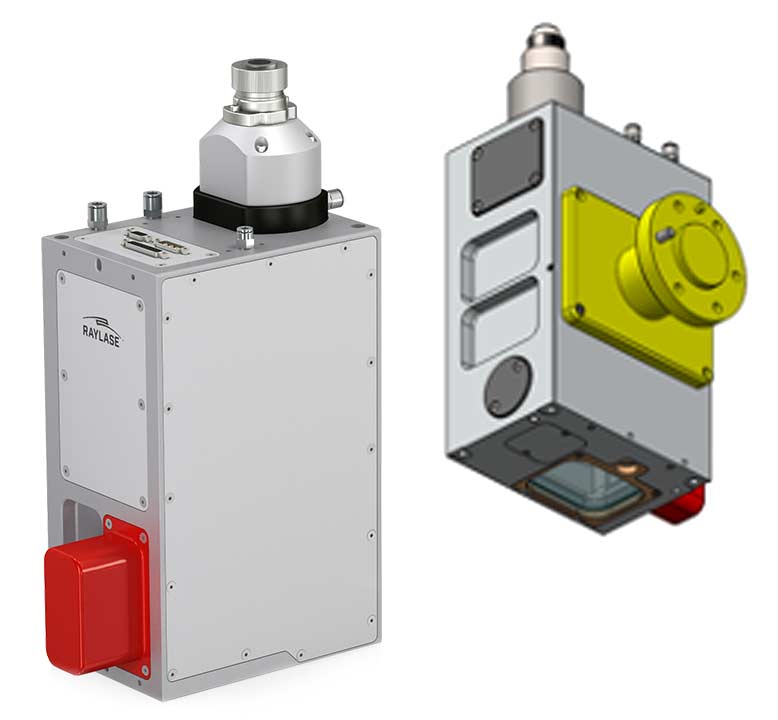
optimum laser welding of different cell formats with the AXIALSCAN FIBER-20 / -30
Your benefits
- Pre-focusing deflection unit with integrated fibre collimator
- Collimator can be designed either vertically or horizontally
- Process light output without wavelength-dependent distortions
- Absolutely dustproof IP64
- Quick-change protection glass
- Laser process fields from 250x250 mm2 to 850x850 mm2 pre-settable
AXIALSCAN FIBER for battery production and quality assurance
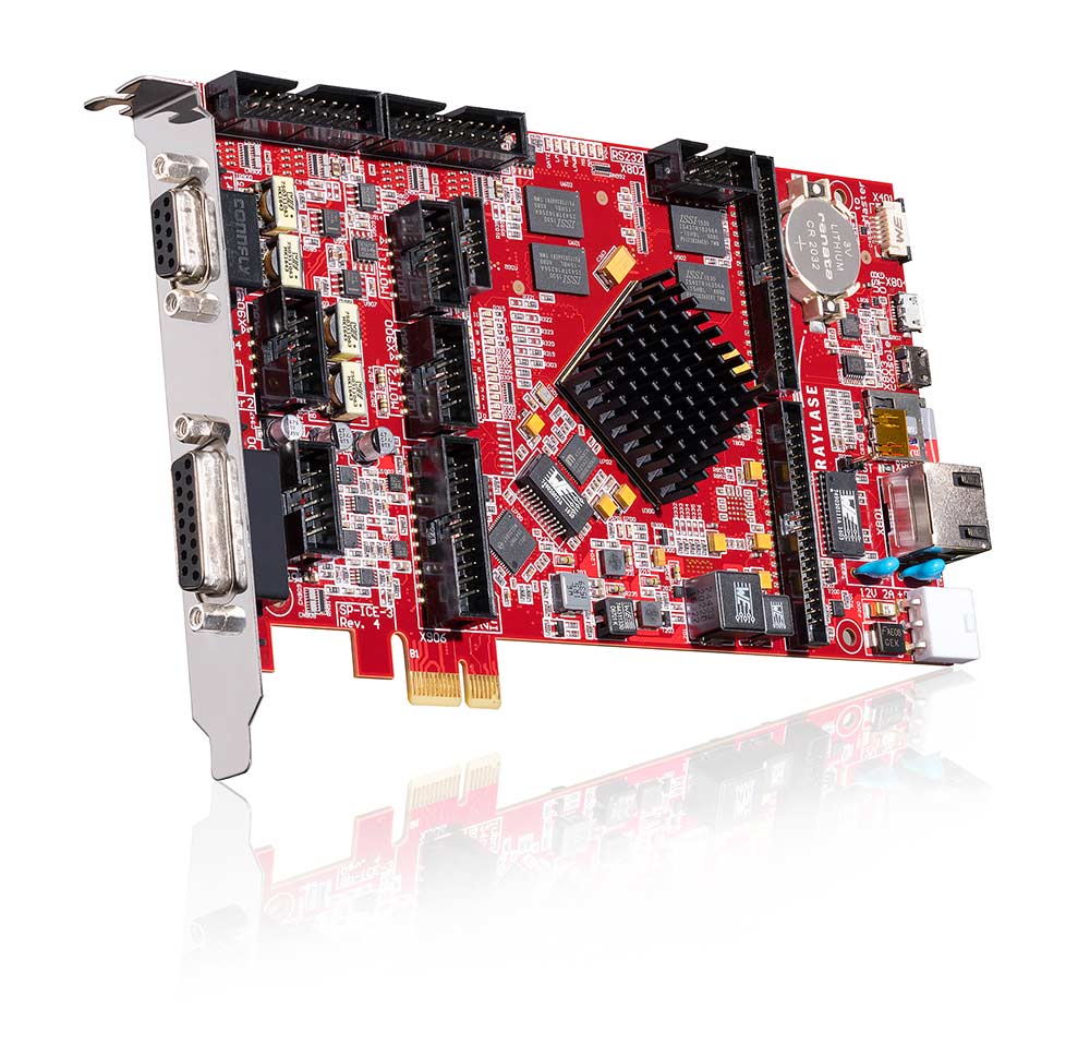
Control Card SP-ICE-3
No AXIALSCAN FIBER-20 / -30 without a control card. It is an essential part of the scanning system and an indispensable control unit for all laser welding processes.
Your benefits
- Welding ramp functions over the entire welding path
- Configurable Lissajous figures
- Stand-alone function without active Ethernet connection to a computer
- Synchronisation of the optical axes of the deflection units
- Feedback signals of the mirror positions of the deflection units
- Automatic speed and position dependent laser power control
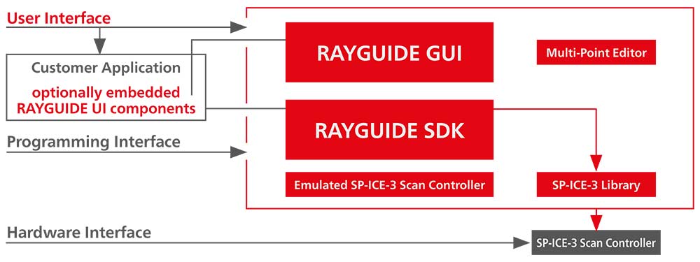
RAYGUIDE LASER PROCESS SOFTWARE
One of the most leading-edge laser process software solutions currently available on the market.
Your benefits
- User-friendly graphical user interface or SDK programming (software development kit)
- ”Embedded GUI“ and ”customer plugins“ possible
- Extensive welding ramp functions
- Management of an unlimited number of control cards
In addition, RAYLASE offers welding modules that have been tried and tested for many years, which work with F Theta lenses and can be more suitable for special specifications.
About the Product
RAYLASE – PARTNERS IN RESEARCH
In the area of laser welding, RAYLASE not only collaborates with machine manufacturers in the automotive industry to understand new process requirements and create new tailor-made products; we also cooperate with universities and institutes on a national and international level. These scientific institutions are especially dedicated to the research of welding processes and their user-oriented industrialisation.
DEFLECTION SYSTEMS – TESTED IN THE FIELD
The renowned Fraunhofer Institute for Laser Technology (ILT) in Aachen is working with the laser deflection unit AXIALSCAN FIBER-30. Dr. Alexander Olowinsky, group leader micro joining, is certain: ”Current laser-based manufacturing processes have become an integral part of battery technology. Laser technology can play out its strengths here particularly in the construction of battery modules and packs consisting of large numbers of cells. Those strengths are high flexibility and good controllability of the energy input for the connection“. The challenges according to Olowinsky will be in process stability and quality: “Here, online process control combined with scanner-based beam guidance systems will be the way to achieve high piece numbers at the required process speeds“.
